1. Object Images and Sound Journey Television
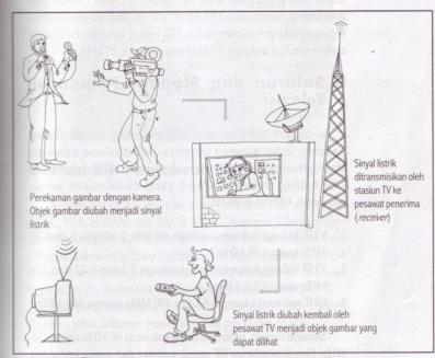
Before we study the working principle of this TV receiver, sebaikknya we must know first how an object image can be accepted by our television receiving equipment. Images that we see is the production of a camera. Object lens camera captured images will be separated into 3 primary colors of red (Red), green (Green) and blue (Blue). Results will be emitted by the TV transmitter (Transmitter) in the form cromynance signal, luminance signal and syncronisasi.
Besides pictures, television transmitters also carry voice signals, image signals are transmitted together. Images transmitted by the system of amplitude modulation (AM), while the sound with a system of frequency modulation (FM). Both systems are used to avoid the noise (noise) and interference.
Notice the image below which explains the way the object image that came to our television receiving equipment.
2. Channels and Standard Television Broadcast
K elompok frequency assigned to the transmission signal is called channel (channel). Each has a 6 MHz channel in one field frequencies (bands) are allocated to commercial television broadcasters, namely:
- Field of low frequency VHF channels 2 to 6 (54-88 MHz).
- Field of high frequency VHF channels 7 to 13 (174-216 MHz).
- UHF channels 14 to 83 (470-890 MHz)
There are 3 TV transmitter systems are as follows:
- National Television System Committee (NTSC) used in USA
- Phases Alternating Line (PAL) used in the UK
- Sequential Couleur a'Memorie (SECAM) used in France
While Indonesia's own use PAL system B. Thing that distinguishes these systems is the image format, the carrier frequency range image and sound carriers.
3. TV Receiver Block Diagram
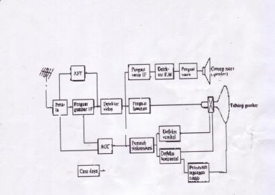
Block diagram Television
M Odel and block type TV series vary, depending on the brand of TV used.
S ecara outline of the block has the following functions:
a) Antenna Television
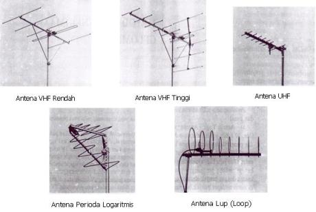
A ntena TV capture RF signals from television transmitters. Antennas are classified based on its construction is 3, ie:
- Yagi Antenna
- Antenna Period logarithmically
- Loop Antenna
Another classification based on the received wave frequency bands are:
- Low VHF Channels
- High VHF Channel
- UHF Channel
The types of antenna in accordance with the Classification:
b) tuning circuit (tuner)
This circuit consists of booster high frequency (HF amplifier), mixer (Mixer) and local oscillator.Tuning circuit functions to receive the incoming TV signal and convert it to IF frequency signal.
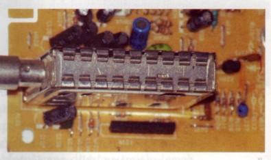 Tuning / tuner
c) The amplifier circuit IF (Intermediate Frequency)
The series serves as a signal booster up to 1000 times. The resulting output signal tuner(Tuner) is a weak signal and very dependent on the distance transmitter, receiver and landscape position. Red circle indicates a partial set of IF tuner inside
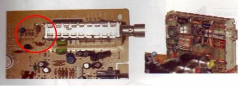
IF amplifier ( red color)
d) Detector Video Series
Functioning as a composite video signal detection that comes out of the picture IF amplifier. It also serves to muffle the sound signal which will result in poor image quality
e) circuit Video Amplifier
The series serves as a reinforcement signal from the detector luminan yangberasal video so it can run a picture tube or CRT (Catode Ray Tube)
f) circuit AGC (Automatic Gain Control)
AGC circuit serves to stabilize its own input television signal's changing so that the output be constant. Red circle indicates the component that resides in some of AGC and some tuner IC
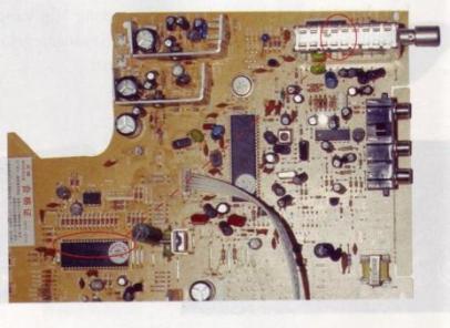 AGC circuit
g) Wave Receiver stabilizer circuit TV.
Stabilizer circuit TV wave receiver such as AGC and the AFT. Automatic Fine Tuning function set the picture carrier frequency of the IF amplifier automatically
h) Synchronization Deflection circuit
This series consists of four blocks namely: synchronization circuit, a series of vertical deflection, horizontal deflection circuit and high voltage generator circuit.
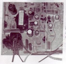 Vertical deflection circuit
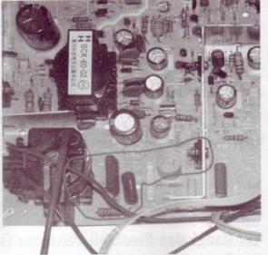
Horizontal deflection circuit
i) The series of Voice
The voice we hear is the work of this series, the sound IF carrier signal is detected by the frequency modulator (FM). Previously, this signal is separated from the carrier signal image
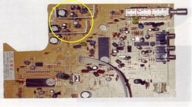
The series of voice / audio
j) Series Power Supply (Power Supply)
Function to convert AC into DC current which then distributed throughout the circuit.
In the figure, the power supply circuit is limited by the white line and red boxes. Areas within the white line is a series of inputs which is a region of high voltage (Live Area) . Meanwhile, the area within the red box is the output power supply which then distributes the DC voltage to the entire TV series
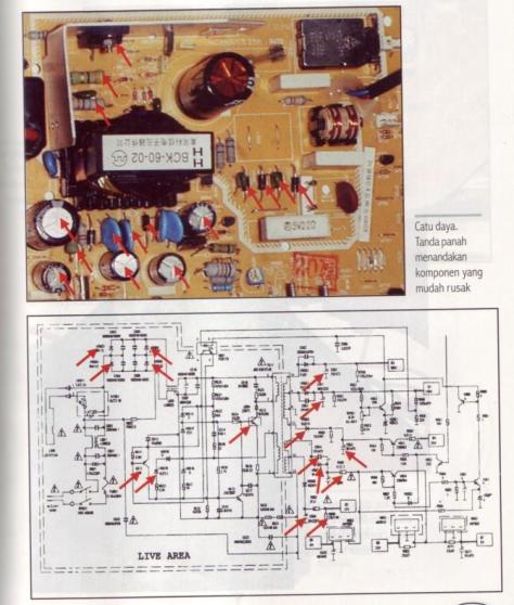
Power Supply Series
k) amplifier Krominan
This amplifier strengthens the signal frequency of 4.43 MHz for krominan are modulated in the signal V (RY signal) and signal U (BY signal). 2 MHz bandwidth amplifier
l) Color Synchronization
In a series of sincronisasi color, the color synchronizing burst signal is removed from the composite color video signal
m) Automatic Color Control (ACC)
If the explosion signal amplitude rises, the ACC issued a steering voltage to minimize the strengthening in the color
o) Color Killer (which create color)
The circuit is useful to suppress the color amplifier, when it is no krominan incoming signal. It happened at the reception is a black and white
p) Phase Switching circuit 180 (splitting Color)
From krominan amplifier, the signal is fed to the color. Splitter (splitting color). It separates the color splitting the modulated signal with the signal V from the modulated signal with the signal U. Splitting the color of PAL switch and some resistors. At the end of each line, during the withdrawal line PAL then rotated 180 V signal. U did not experience signal phase rotation
q) The color demodulation
Using a color demodulator, then the color difference signals in demodulasikan of the signal U and V. Because the transmitter, the signals were modulated with a carrier system suppressed / eliminated and only the second sub-carrier side line (side band sub carrier) that exist. In order to mendemodulasikannya carrier signal into the original color back, then needed a sub carrier 4.43 MHz with phase and the exact same frequency as the transmitter
4. Summary
- Power supply provides the voltage throughout the amplifier
- Tuner receives signals from the antenna and to strengthen and change the frequency of the received signal into the IF (33.4 MHz and 38.9 MHz). Sub-carrier signal is carried by the IF signal Videos
- IF amplifier and detector row strengthen IF signal and detects the video signal. Sound IF signal is also produced in this detector after 33.4 MHz IF signal and 38.9 MHz are mixed in the video detector
- Sound IF signal is amplified by IF amplifier noise and detected by FM detector
- Strengthen the audio amplifier audio signals from the FM detector. Then the audio signal is converted into sound by a loudspeaker
- AGC circuit set the RF and IF amplifier strengthening vidio, vidio fixed so that the output signal amplitude
- Vidio signal detection result strengthened and incorporated into the cathode CRT
- Sebahagian video signal sync pulses are separated
- Horisoltal synchronization pulses supplied to the horizontal oscillator via the AFC
- 10. Vertical synchronization pulse triggering for synchronous vertical oscillator
- Pembelok signal into vertical and horizontal deflection coils and coil convergence
- Sub-carrier signal through the amplifier band pass was taken from the video amplifier
- After the demodulation process by a series of chroma chroma signal is obtained (B - Y) and (R-Y)
- In a series of matrices generated signal (G - Y) of the signal B - Y) and (R - Y)
- Y signal and the signal on the cathode CRT (R - Y), (G - Y) and (B - Y) gives the influence of electron beam between cathode and grid in accordance with the signals R, G and B

Tidak ada komentar:
Posting Komentar